How Schroeder Diffusers Work: The Math Behind QRD Scattering
Explore how Schroeder diffusers use quadratic residues and reflection phase, what Fourier theory predicts, and how polar response reveals real limits.
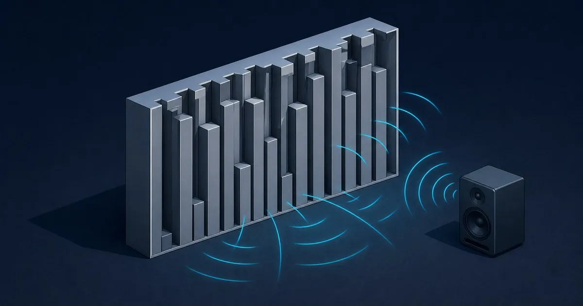
A quadratic residue diffuser is a reflection phase grating: a patterned surface that changes the relative timing of reflected sound. Its unequal wells create phase differences across the face. The mathematical question is why a sequence based on squared integers can distribute sound across directions more evenly than a flat surface.
Schroeder diffusers connect number theory with wave interference. This guide follows that connection through the residue sequence, the Fourier transform and the polar response. For dimensions and fabrication arithmetic, use the separate QRD well depth tables and formula.
From a well to a reflection phase
Sound entering a rigidly terminated well travels inward and back out. A well of depth d therefore adds a round-trip path of 2d. Relative to reflection at the opening plane, that path corresponds to a phase difference with magnitude 4πd/λ, where λ is wavelength.
In the ideal model, each well returns a wave of equal amplitude but a different phase. Adding the returns gives interference: reinforcement in some directions and cancellation in others. The far-field pattern depends on those relative phases, the spacing of the wells and the overall size of the surface.
This assumes narrow wells, rigid boundaries and negligible losses. The reflection phase grating treatment in the cited JAES paper is a model for a physical surface; it does not make every wooden panel an equal-energy scatterer at every angle.
Why n² mod N is used
For an odd prime N, the residue sₙ = n² mod N is the remainder after dividing the squared well index by N. Index one period from zero through N − 1. A QRD assigns relative phases proportional to those residues.
At the design frequency, the ideal reflection coefficients can be written as rₙ = exp(i2πsₙ/N). Choosing the opposite sign convention reverses the phase progression without changing the constant-magnitude property discussed below. All these complex numbers have magnitude one: the model changes phase while keeping reflected amplitude constant.
Order matters. A sorted list of the same depths has the same material requirements but generally a different angular response. The useful property belongs to the spatial sequence, not just to the collection of depths.
What the constant-magnitude Fourier transform means
The discrete Fourier transform sums those complex reflection coefficients with a phase weighting for each spatial order:
Rₘ = Σ rₙ exp(−i2πmn/N), summing n from zero through N − 1.
For the ideal quadratic-phase sequence with odd prime N, the unnormalised transform has magnitude √N for every discrete order m. Dividing the transform by N gives magnitude 1/√N and squared magnitude 1/N. The normalisation must be stated; amplitude and energy fractions are different quantities.
This constant magnitude is the attraction of the residue construction. At the sampled orders of the ideal model, no one order is favoured by the sequence’s Fourier magnitude.
It does not mean that the continuous polar response of a finite panel is perfectly uniform. Well apertures shape the radiation, finite edges diffract sound, and only propagating orders can carry energy away. Incident angle also changes the geometry. Equal discrete Fourier magnitudes are a design property, not a substitute for an angular measurement.
Design frequency and the return of coherent reflection
The phase relationship changes with frequency because wavelength changes. At the design frequency, the chosen depths produce the intended quadratic-phase progression. At integer harmonics not divisible by N, the ideal prime-length sequence retains a related equal-magnitude transform.
At a multiple of N times the design frequency, every well’s extra path corresponds to a whole number of cycles. The ideal well returns then line up in phase again. This is the phase-repetition limitation discussed in the diffuser review.
Real bandwidth also depends on aperture width and panel size. Below the intended operating region, the available depth differences become small relative to wavelength. At high frequencies, transverse modes in wells can invalidate the simple plane-wave approximation. None of these changes is a universal sharp on/off boundary for an installed panel.
The numerical consequences belong in the bandwidth sizing reference and the diffuser calculator.
Reading a polar response
A polar response plots reflected level against direction at a stated frequency and incident angle. It shows where sound goes after reaching the surface.
A strong peak near the mirror-reflection direction indicates a concentrated specular return. Several peaks show redistribution into lobes; they do not by themselves establish uniform diffusion. Compare plots across frequency rather than choosing the one band with the flattest appearance.
Repeated identical panels introduce another spatial period. The resulting array can favour narrow angular lobes even if one isolated period has a useful response. Evaluate the intended assembly, including gaps and neighbouring surfaces. Mirroring a residue sequence is not a general guarantee of removing periodicity.
Panel size also matters when interpreting a plot. A small flat reference already scatters at its edges. Comparing a diffuser against an equally sized flat surface helps separate that edge contribution from the benefit of the designed relief.
ISO 17497-2 and diffusion quality
The directional diffusion coefficient describes angular uniformity. ISO 17497-2 specifies a free-field measurement method for this property.
Scattering and diffusion describe different aspects of a surface. Scattering concerns energy leaving the specular component; diffusion concerns how evenly reflected sound is distributed. A surface can redirect substantial energy into a few directions without distributing it uniformly.
A meaningful comparison therefore includes frequency, incident angle, sample dimensions, reference surface and measurement geometry. A single coefficient without those conditions says less than a set of comparable curves. A quieter reading at one microphone cannot establish whether sound was scattered, absorbed or sent elsewhere.
What construction changes
The equal-amplitude assumption is approximate. Air in narrow cavities can lose energy, and flexible walls, porous well floors or leaking joints can change the response. The cited Applied Acoustics paper investigates absorption in constructed QRDs.
Well direction is another limit. A row of vertical wells primarily varies the surface horizontally, whereas a two-dimensional block array varies it in both directions. The comparison of acoustic diffuser types explains that distinction without requiring another depth calculation.
For the construction details, see how to build a QRD diffuser. For the broader choice between reducing reflected energy and redistributing it, start with absorption versus diffusion.
Sources
- Schroeder Diffusers: A Review (Building Acoustics, 2003)
- Binaural dissimilarity and optimum ceilings for concert halls: More lateral sound diffusion (JASA 65, 1979)
- Diffuse sound reflection by maximum-length sequences (JASA 57, 1975)
- The Reflection Phase Grating Diffusor: Design Theory and Application (JAES 32, 1984)
- Absorption characteristics of a practically constructed Schroeder diffuser of quadratic-residue type (Applied Acoustics 35, 1992)
- ISO 17497-2:2012, Sound-scattering properties of surfaces: measurement of the directional diffusion coefficient in a free field
Related

QRD N7, N11, N13 and N17: Well Depth Tables and Formula
Use the QRD well-depth formula and worked N7, N11, N13 and N17 tables to choose a prime from design frequency, well width or maximum panel depth.

Types of Acoustic Diffusers: QRD vs Skyline vs BAD
How one-dimensional wells, two-dimensional block arrays and binary amplitude panels differ in scattering plane, depth, absorption and best placement.

Acoustic Diffusers: How They Work vs Absorption
Learn how acoustic diffusers redistribute reflections, how diffusion differs from absorption, and which measurements help assess a panel for a room.